
CPM-BS CPM-BS
Eingestellt / EOL
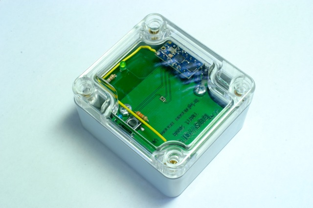
The CPM-BS is a kit. You receive the PCB with brightness sensor soldered in as well as a CPM module.
Brightness sensor - based on CPM
General
The CPM-BS is a kit. You receive the PCB with brightness sensor soldered in as well as a CPM module.
How to build
Required parts
The do-it-yourself version of CPM-BS consists of the PCB with on-board brightness sensor and the CPM module (Buy it here). Most of the additional parts you need to complete the brightness sensor can be bought from the electronics distributor Reichelt:
- Batteriehalter für 2 Microzellen (AAA), Lötfahnen: \tHALTER 2XUM4-NLF
- LED 2, 3mm, Low Cost, grün:\t\t\t\tLED 3MM GN
- R11 680 Ohm: \t\t\t\t\t\tMETALL 680
- R1 (see calculation below):\t\t\t\tMETALL 40,2K
- C1,C2 100 nF:\t\t\t\t\t\tX7R-2,5 100N
- SMD-Kurzhubtaster, vert. Montage, Höhe 5,0mm:\tTASTER 9315
- 40pol. Stiftleiste, gerade, RM 2,54:\t\t\tSL 1X40G 2,54
- IC-Adapterleiste RM 2,54mm: \t\t\t\tAW 122/20
- Distanzhülsen, Metall, 6-Kant, M3, 15mm:\t\t\t\tDI 15MM
- Zylinderkopfschrauben 100st. Schlitz M3x10mm:\t\t\t\tSZK M3X10
Box
The PCB is 57mm x 51mm in size and fits in a G201C plastic case with transparent cover (datasheet) from ELV (Best.Nr. 68-305-28).
Assembly tips
You need some experience in soldering, but there are no SMD parts to solder. Use an extra fine tip on your soldering iron, especially for soldering the CPM module on the 2x7 pin header.
To make the ISP pinheader, cut off 2 x 3 pins from part SL 1X40G 2,54.
Cut off 2 x 7 pins from part AW 122/20 to solder the CPM module onto the PCB.
To fix the PCB in the box mount the two distance pieces with screws on the PCB and glue the distance pieces to the bottom of the box. You have to remove the plastic mouting sockets ar the bottom of the box because otherwise the device will not fit in.
Antenna
The length of the lambda/4 wire antenna for 868,35 MHz is 86 mm.
RExt calculation
The ISL29102 has responsiveness that is a square-root function of the light intensity intercepted by the photodiode in lux. Because the photodiode has a responsivity that resembles the human eye, conversion rate is independent of the light source (fluorescent light, incandescent light or direct sunlight).
The output voltage VOut is a function of the light intensity E (given in lux) and the value RExt of the external resistor:
VOut= 1.8muA*sqrt(E/100lux)*RExt
RExt is used to set the light-to-voltage scaling constant. The compliance of the ISL29102’s output circuit may result in premature saturation when an excessively large RExt is used. The output compliance voltage is 700mV below the supply voltage VDD.
VDD is measured by the AD converter of the ATtiny84 aboard the CPM module. Note that VOut is measured relative to the reference voltage VRef of the ATTiny84. The reference voltage Vref is 1.1V so make sure that VOut does not exceed 1.1V even on very bright days or the measured value will be limited by the saturation.
A sunny summer day gives far more than 100,000 lux. With a choice of RExt= 12kOhm, the maximum brightness you can measure is
E= (Vref/RExt/1.8muA)**2*100lux= 259,345lux
For evaluation purposes the resistor RExt can be replaced by a 50kOhm trimmer (part PT 6-L 50K: Einstellpotentiometer, liegend, 6mm, 50 K-Ohm from Reichelt).
Firmware
Download
The firmware is available from Berlios:
CVS: http://cvs.berlios.de/cgi-bin/viewvc.cgi/culfw/culfw/Devices/CPM-BS/
Download bsfw.hex.
Internals
In normal operation, the brightness sensor measures and transmits the brightness every 2 minutes. For transmission the FS20 sensor protocol is used. The house code is fixed to A5CF, the device code is the sensor number which runs from 1 to 9.
The brightness value is transmitted as 1024*VOut/VRef. This can be converted into the unit lux as follows:
E= 100lux*(VOut/RExt/1.8muA)**2
with
VRef= 1.1V and VOut= VRef*brightness value.
User manual
After powerup, the device reads its sensor number from the EEPROM. Possible sensor numbers are 1 to 9.
The first ten transmissions (prelude mode) come every 8 seconds, then \tthe transmission interval changes to 2 minutes (normal operation).
To enter configuration mode hold down the button on the device until \tthe LED comes on - this should take at most 8 seconds. Release the button then. The LED will indicate the sensor number (blink once= sensor number 1, blink twice= sensor number 2, etc.). There is a one second pause between subsequent blink sequences. If you press and release the button in the pause the sensor number is increased by one. The sensor number wraps around from 9 to 1. If you do not press the button for ten pauses, the device re-enters prelude mode followed by normal operation after ten transmissions.
Documents
- Brightness sensor ISL29102 - data sheet
- 868MHz transceiver module with processor - product page
- Schematics (PDF)
- Layout (PDF)
- Eagle files: Bright.sch / Bright.brd
- Image Gallery